G75 Groove Cycle

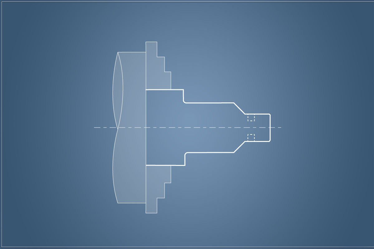
When machining grooves on our turned part, we can use G01 to position our tool and cut the feature. By using the G75 grooving cycle we can speed up this process especially if the groove is wider than our tool.
What is the G75 groove cycle?
By stating the position of our groove, the depth and the width. The G75 cycle takes care of the rest and produces our feature for us with a minimum amount of code. This speeds up the process and makes adjustments to the part easy.
How the G75 grooving cycle works

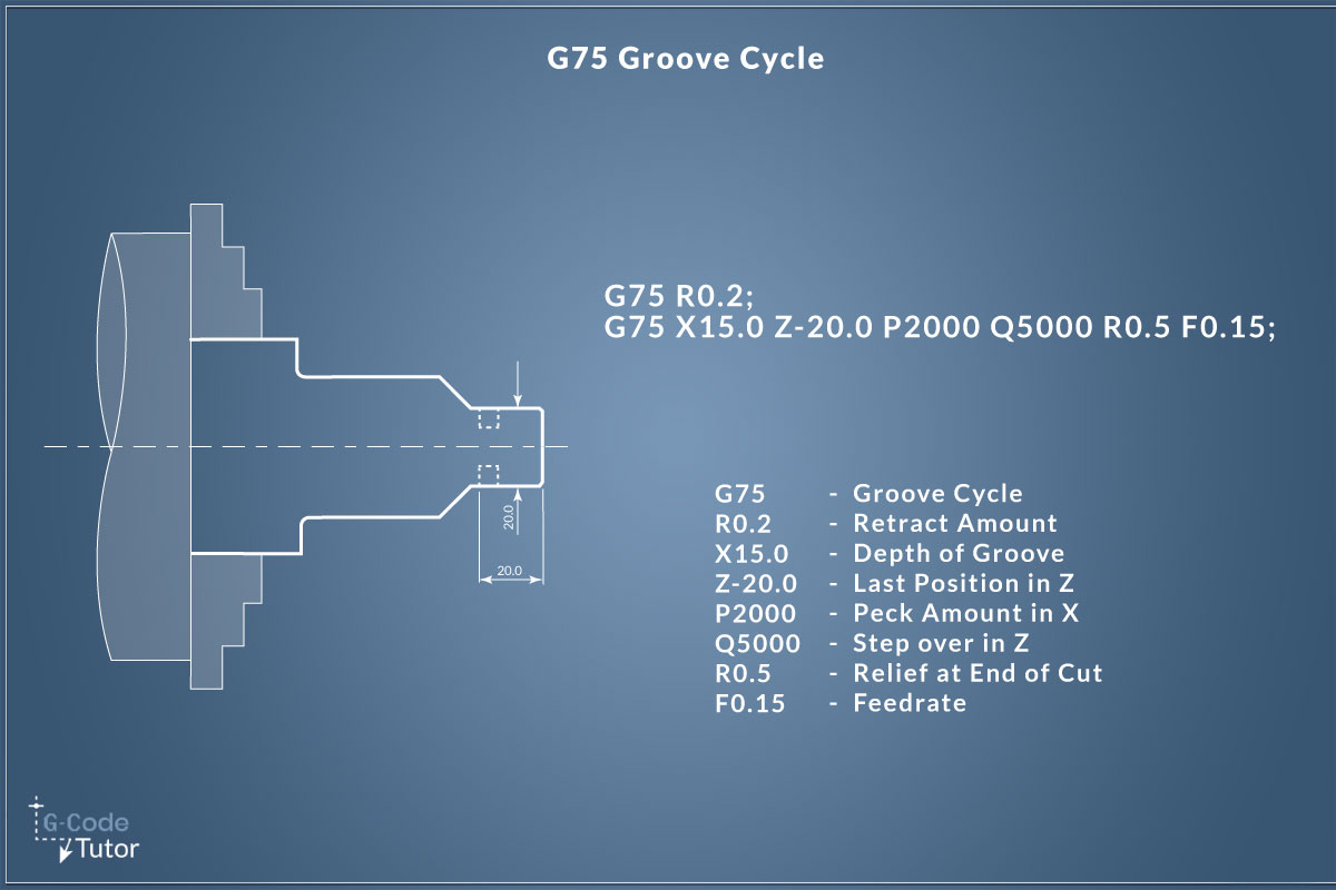
An explanation of the two-line G75 cycle block.
Each part is broken down and explained below.
G75 R(1);
G75 X Z P Q R(2) F;
G75 - Grooving Cycle
R(1) - Retract Amount
X - Final Depth of Groove
Z - Final Position in Z
P - Peck Amount in X (Microns)
Q - Stepover Distance in Z (Microns)
R(2) - Relief at End of Cut
F - Feed Rate
G75 tells the machine that we wish to use the groove cycle
The first 'R' word defines the retract amount of each pass in the X-axis. The machine will pull the tool out of the groove to this distance after each peck.
The 'X' distance lets the control know the final diameter of our grooving tool.
The 'Z' distance is the final position of the groove taken from the datum, we position the start point of the groove by using G00 or G01 before we activate the cycle.
By using the 'P' word we can define a peck distance, this is optional but useful if we are cutting certain materials.
If our groove is wider than our tool, by using this cycle we do not have to buy in custom tooling to match the size of our groove. The 'Q' word allows us to step over after each cut to accurately machine the width to the required size. If we need to adjust this, we do not have to buy in a new tool. We just simply change this value.
'R' allows us to add a relief at the end of the cut, this can also be omitted.
G75 Single-Line Example

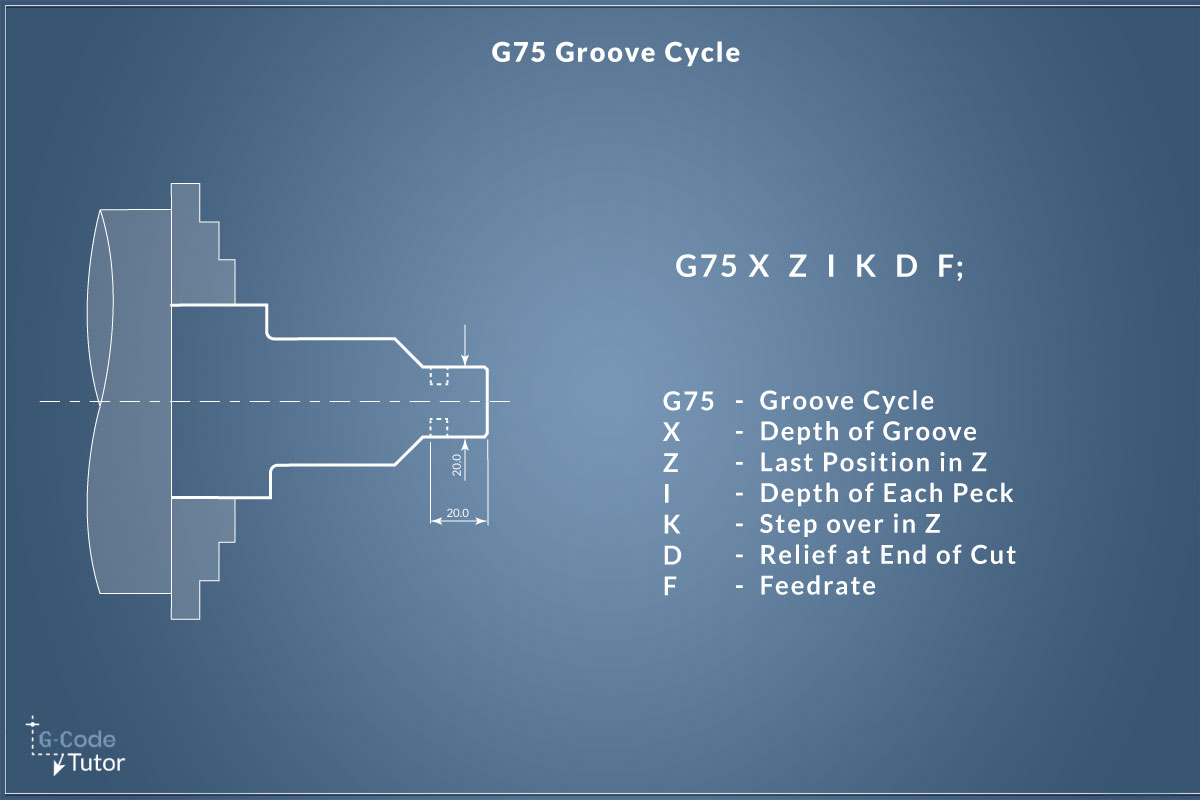
This cycle is also available in a single-line format. Depending on the version of FANUC controls that is being used will depend on which version of this cycle we program.
G75 X Z I K D F;
G75 - Groove Cycle
X - Depth of Groove
Z - Last Position in Z
I - Depth of Each Peck
K - Stepover in Z
D - Relief at End of Cut
F - Feed rate
G75 Tells the machine controls that the following information applies to a groove cycle
'X' defines the final diameter of our groove.
As before in the 2 line example, 'Z' is our final position of the feature being machined.
With the single-line version, we use 'I' to define each peck. For example, if we set this to 1000 then the tool will retract after removing 1mm of material.
After each peck is at its final depth, by stating a 'K' word we can step over the amount defined to cut the next peck along the Z-axis.
'' D' is our relief at the end of the cut.
Finally, we state the feed rate with an 'F' word
By using cycles such as this grooving cycle, we can reduce the time it takes to write our G-Code and simplify any changes we need to make in our code to produce a correct part. On a CNC lathe, we can often produce our programs much quicker than by using CAD/CAM as we do not have to make models and edits are a quicker process as we can do them at the machine controls.
Share this article
For a complete tutorial on CNC Lathe Programming check out my course.
The quickest way to learn CNC Programming


