CNC Lathe Programming - Cycles
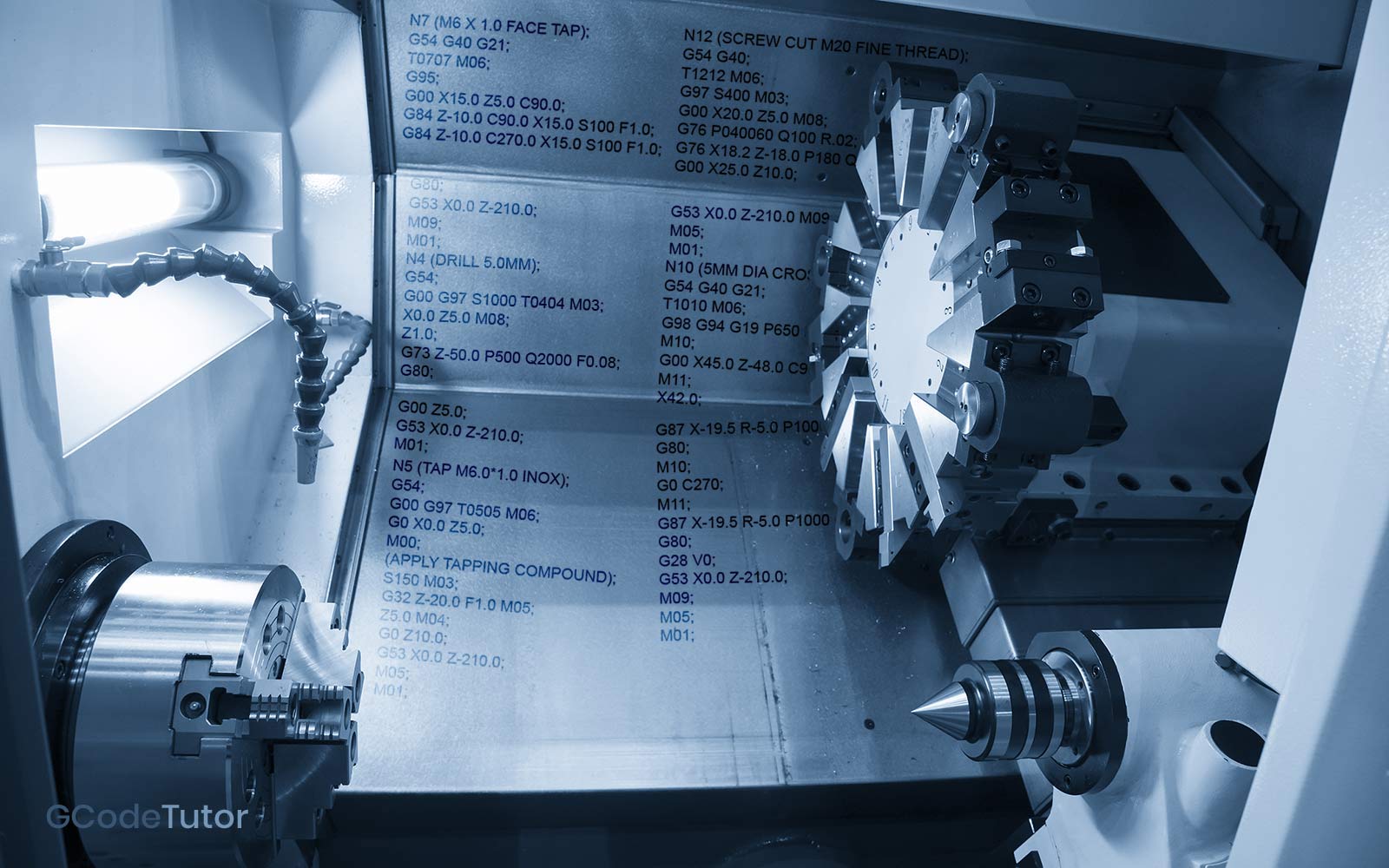
Repetitive cycles are used in CNC Lathe Programming to minimise the amount of code that has to be written and give us more control over complex shapes and operations. The control system will understand the operation and perform the repetitive cycle following the commands that are given by the programmer until the feature is complete.
G70 - Finishing Cycle
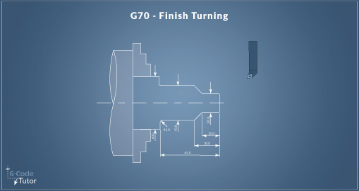
G70 P Q;
Example:
G00 X70.0 Z2.0;
G42;
G70 P100 Q200;
G00 X70.0 Z5.0;
G53 X0.0 Z-210.0 M09;
G40 M05;
This cycle is used after one of the roughing cycles and follows the contour programmed within that roughing cycle. The'P' and 'Q' values are used to locate the profile in that cycle and run a finishing cut that follows it.
G71 - Roughing Cycle
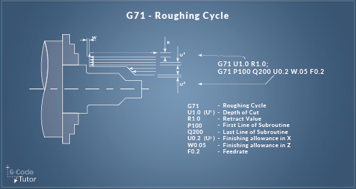
G71 U R;
G71 P Q U W F;
Example:
G71 U1.0 R1.0;
G71 P100 Q200 U0.2 W.05 F0.2;
N100 G00 X19.0;
G01 G42 Z0.0 F0.2;
Z-65.0 ,R5.0;
X60.0;
N200 G40 X70.0 Z5.0 F200;
The G71 roughing cycle follows the contour that is programmed between the N numbers. It is used to remove material by cutting along the Z-axis leaving some material on for a finishing cut using a G70 cycle.
Learn more about the G71 Roughing Cycle here
G72 - Facing Cycle
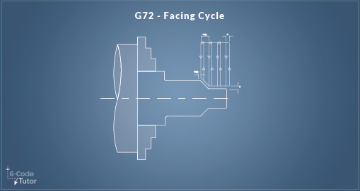
G72 W1 R;
G72 P Q U W2 F;
Example:
G72 W1000 R100;
G72 P100 Q200 U0.03 W0.03 F0.01;
N100 G00 Z-0.2 S500 P11;
G01 X3.0 F0.01;
X2.0 Z-0.5;
Z-0.1;
X0.5;
N200 X0.0;
The G72 roughing cycle follows the contour that is programmed between the N numbers. It works the same as the G71 cycle but is used to remove material by cutting along the X-axis.
Learn more about the G72 Facing Cycle here
G73 - Pattern Repeating Cycle
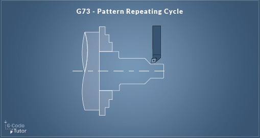
G73 U(1) W(1) R;
G73 P Q U(2) W(2) F;
Example:
G73 U0.5 W0.2 R0.03;
G73 P100 Q200 U0.4 W0.01 F0.01;
N100 G00 X1.0 S1000 P11;
G01 Z-0.4 F0.01;
X2.0 Z-1.0;
Z-1.5;
N200 X4.0;
The G73 cycle is a pattern repeating roughing cycle used in boring or turning. It is followed by the G70 finishing cycle.
Learn more about the G73 Pattern Cycle here
G75 - Peck Grooving Cycle
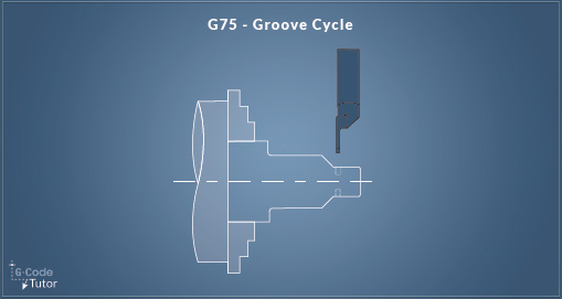
G75 X Z P Q F;
Example:
G00 X3.0 Z-6.0;
G75 X2.0 Z-1.0 P0.1 Q0.15 F.002;
G00 X10.0 Z12.0;
The G75 cycle is used to groove out an area larger than the grooving tool.
G76- Screw Thread Cycle
(Single Line)
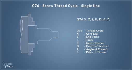
G76 X Z I K D A F;
Example:
G97 S400 M03;
G00 X20.0 Z5.0 M08;
G76 X18.2 Z-18.0 I-.01 K900 D100 A60 F1.5;
G00 X25.0 Z10.0;
If the parameters of the machine are set up correctly, you can use one block to machine a screw thread. Note this might not work on every lathe or machining centre so the following method has been included
G76- Screw Thread Cycle
(Double Line)
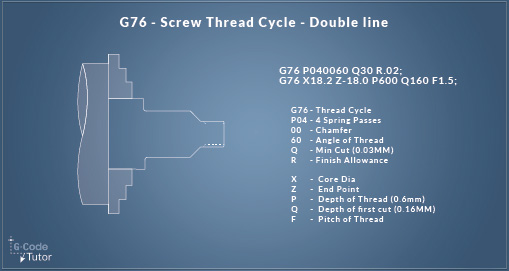
G76 P (1) (2) (3) Q R;
G76 X Z P Q R F;
Example:
G00 X20.0 Z5.0 M08;
G76 P040060 Q100 R.02;
G76 X18.2 Z-18.0 P180 Q160 F1.5;
G00 X25.0 Z10.0;
The more common two-line format of the G76 screw cutting cycle when CNC lathe programming
Learn more about the G76 Thread Cycles here
G83 - Z-axis Peck Drilling Cycle
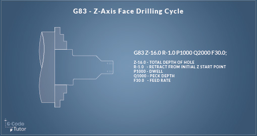
G83 Z Q R P F ;
Example:
Z1.0;
G83 Z-50.0 P500 Q2000 P1000 F0.08;
G80;
The G83 peck drilling cycle is used with live tooling to drill offset from the centreline on the Z-Axis.
G84 - Z-axis Tapping Cycle
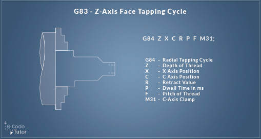
G84 Z Q R F;
Example:
X0;
G84 Z-5.0 Q2000 R1000 F0.0625;
G80 G0 X5.0;
The G84 cycle is used for tapping along the Z-axis when not tapping in the centre line of the part.
G87 - X-axis Peck Drilling Cycle
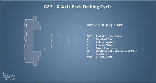
G87 X R Q P F;
Example:
X42.0;
G87 X-19.5 R-5.0 P1000 Q2000 F30;
G80;
The G87 cycle is used for peck drilling on the X-axis with live tooling.
G88 - X-axis Tapping Cycle
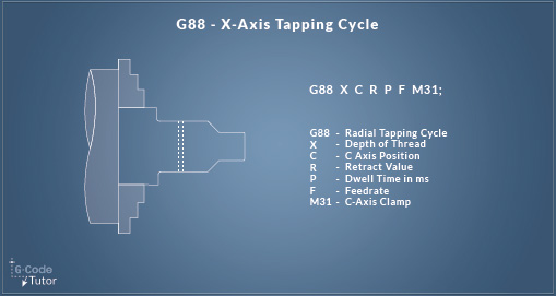
G88 X R Q P F;
Example:
X42.0;
G88 Z-48.0 C90.0 X30.0 R42.0 P200 S100 F1.0;
G80;
The G88 cycle is used for tapping on the X-axis with live tooling.
Share this article
For a complete tutorial on CNC Lathe Programming check out my course.
The quickest way to learn CNC Programming
