G98 and G99 G Codes
When programming a CNC milling machine using canned cycles, the machine reads the G Code without considering any objects that we may have added to the component. For example clamps. Below we look into a method using G98 and G99 to lift the cutter over such obstacles.
Safe rapid distance
The G Codes G98 and G99 are used to lift the cutter to different heights during a canned cycle on a CNC milling machine.
On lathes, these G Codes are used to set the feed rate mode, so this lesson concentrates on programming a CNC mill.
When we use G98 the machine rapids back to the Z position set within the program, when we use G99 the tool retracts back to the position that we define as R within the cycle. Lets have a look at how this is achieved by using an example of a G82 counterbore cycle.
An Example

Let's take a look at the G82 cycle from this part program
Z15.0 M08;
G82 G99 Z-4.0 R1.0 P500 F50.0;
X20.0;
G98 X40.0;
G99 X20.0;
G80;
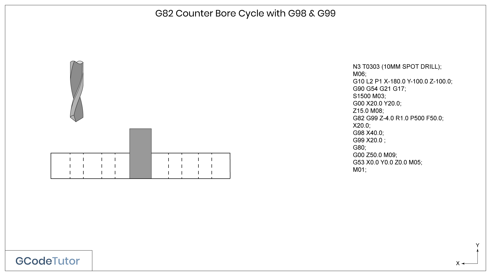
This cycle counterbores the four holes shown in the diagram. We could set the retract value above the clamp and the holes would be machined perfectly fine, but to speed up the cycle time we need to minimise the distance that the drill retracts between each hole. As you have probably guessed we do this by using the G98 and G99 G Codes
If we removed the G98, G99 and the R value (retract value) from the program, the machine would default to retracting to the Z15.0 position that we defined on the first line.
I am taking our Z datum position to be the top of the component so it would return to 15mm above the surface after each counterbore is produced.
That's 14mm of movement for each hole that is wasting machining time just because a clamp is between holes two and three. It might not seem a lot when we are machining just four holes but imagine the time lost when drilling over 100 holes!
The G98 and G99 G Codes

Here is this program explained line by line
Z15.0 M08;
First, we bring the drill down to 15mm above the surface of the material and turn on the coolant with M08
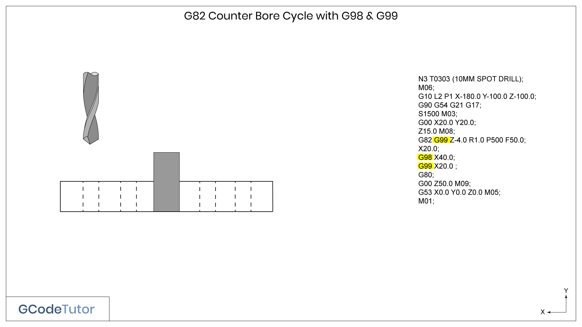
G82 G99 Z-4.0 R1.0 P500 F50.0;
This line sets our counterbore canned cycle by using G82 and sets the movement to our hole with G99, this tells the machine that once the first hole is drilled to retract to the R1.0 value and not the Z15.0 set by the line above.The Z-4.0 is the depth of the counterbore
The P500 value is the dwell time that is set to 500 milliseconds that will take place once the drill has reached the bottom of the hole.
F is our feed rate in mm/min.
X20.0;
This is the distance from the first hole to the second along the X axis, it is taken as an incremental move and can include a Y movement and an optional Z depth if the depth of the hole differs from the first. The G99 code is still active from the line above so the drill will retract to 1.0mm above the surface as defined by the R value.
G98 X40.0;
This line drills our third hole 40mm in the plus direction along the X axis. It retracts to Z15.0 above the surface of the part after drilling the previous hole. The G98 code tells the control that we wish to ignore the retract value of 1mm that we defined by R in our canned cycle line and to return to the Z15.0 distance. Safely above our clamp.
G99 X20.0;
The final hole is drilled 20mm in X from the last hole, the G99 code tells the machine to retract back to the R position and not the Z position.
G80;
The G80 command is the G Code we use to tell the control that the canned cycle has ended.
It is common to make the mistake of putting the G98/G99 on the wrong line. An easy way to remember it is that we add it to the hole position after the obstacle and not on the hole position before.
Share this article
To learn the basics of G Code programming, check out my Foundation course
The quickest way to learn CNC Programming


