G73 and G83 drilling cycles
Both the G73 and the G83 drilling cycles are capable of peck drilling. The main difference is that the G73 pecks does not return above the face of the material during each peck, but instead backs off the cutting face to break the swarf chips then reapply pressure to continue the cut. Below we look at how both cycles can be programmed and the situations where we would need to use each one.
We can have even more control on some machines by using variable peck drilling. This is a feature that we can use to define the size of each peck that removes less material on each cut to increase tool life, break the swarf chips and helps get coolant down to the bottom of the hole. If we are not using through spindle coolant this is a very useful technique. I also cover this in this article.
G83 peck drilling cycle
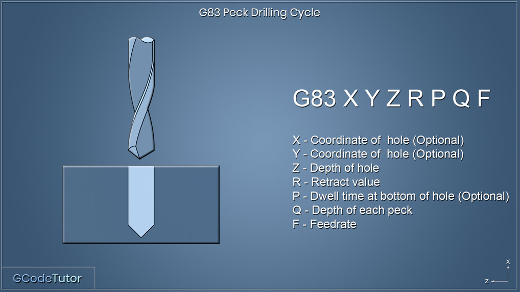
G83 X Y Z R P Q F
The G83 peck drilling cycle retracts above the surface of the component after each peck. The retracted height is controlled by the value R within the line of code.
This technique is used when a build-up of swarf is present during the cutting operation and needs to be cleared. Using high-pressure coolant directed on the tip of the tool helps wash away the build-up of chips on the tool during the pecks and also allows for coolant to reach the bottom of the hole to promote both lubrication and cooling.
G73 peck drilling cycle
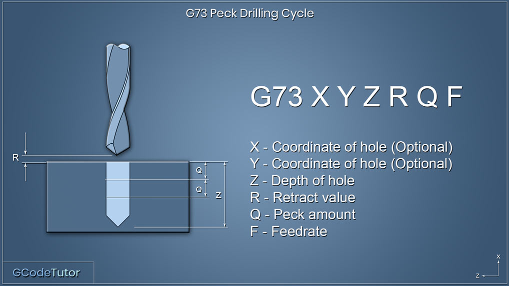
G73 X Y Z R Q F
The G73 peck drilling cycle works in a similar way as the G83. The main difference is that each peck does not return to a clearance position above the hole, instead, the drill retracts to a set distance within the hole. This acts as a chip breaker and is often referred to as a chip breaking cycle. This cycle is often used when drilling with long series drills that may be prone to vibration. By keeping the drill inside the hole during pecking the machining time is quicker especially when drilling many holes.
The Q value in this cycle refers to the distance that the drill cuts between each peck. The retract distance is set within the machine parameters which is typically 1.0mm.
Using I, J and K to variable peck drill
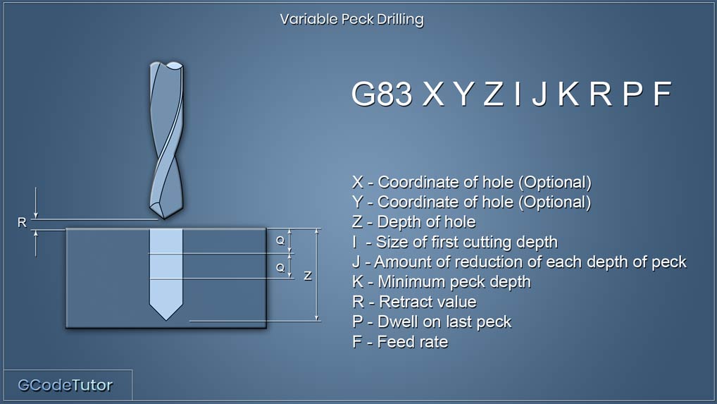
G83 X Y Z I J K R P F
On some controls it is possable to have more control over the pecking cycle. By using the I, J and K values we can decrease the amount of material removed on each peck. This is used for deep hole drilling and when drilling hard materials.
The first drill depth before it retracts is defined by 'I' each drill depth after this will be reduced by the amount 'J' This will keep reducing in size until the minimum depth has been reached which we state with 'K'
Lets see how this looks within a program.
Z15.0 M08;
G83 X10.0 Y10.0 Z-15.0 I5.0 J1.0 K1.0 R5.0 P500 F50.0;
X40.0;
G98 X60.0;
G99 X40.0;
G80;
Take a look at the G83 line where all the action happens. The X and Y positions tell the machine where the first hole position is in relation to the datum, This is optional. If these dimensions are not added on this line the control will assume that the drill is already in position. The 'I' value dictates the amount of material the first peck will remove, in this case, we are drilling 5mm before our first retract. The next peck will remove 4mm. We know this as the 'J' value is set to 1mm so it will decrease the amount drilled by 1mm on each peck. Once the peck size reaches 1.0mm (K) it will stop decreasing the amount of material removed and will keep drilling at 1mm between each peck until the final depth of the hole has been archived. The 'P' adds a half a second dwell once the drill is to depth, this helps clean up the bottom of the hole if we are drilling a blind hole, this can be omitted if not required. The 'P' value is in milliseconds hence P500 and not P0.5
It should be noted that different controls may handle this in different ways and this example is a general overview. It is always recommended to read the machine manual to see the exact way your control handles variable peck drilling.
Share this article
For a complete tutorial on CNC mill Programming check out my course.
The quickest way to learn CNC Programming

