CNC Mill Programming - Cycles
Canned cycles are used when programming CNC mills to minimise the amount of code that has to be written and give us more control over complex shapes and operations. The control system will understand the operation and perform the canned cycle following the commands that are given by the CNC programmer until the feature is complete.
G81 - Drilling Cycle
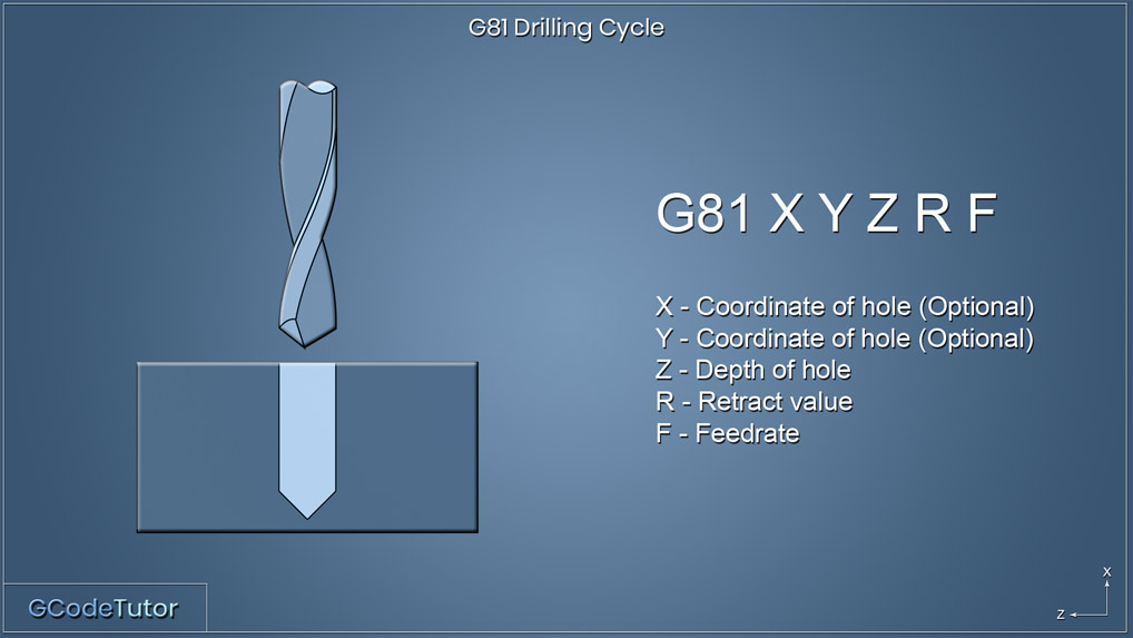
G81 X Y Z R F;
Example:
G81 Z-12.0 R1.0 F50.0;
X50.0;
X50.0;
Y40.0;
G80;
This cycle is used when drilling a series of holes when a dwell or peck drilling is not needed. This is the most basic drilling cycle used on a CNC milling machine.
The X and Y dimensions are optional if they are omitted on this line the machine expects the spindle to be in the position of the first hole.
G82 - Counter Bore Cycle
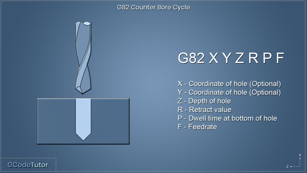
G82 X Y Z R P F;
Example:
G82 Z-12.0 R1.0 P500 F50.0;
X50.0;
X50.0;
Y40.0;
G80;
The G82 counter bore cycle is used when a dwell is needed at the end of each Z movement. Normally used when centre drilling, spot drilling or machining a flat bottom hole.
The 'P' Word defines the time of the dwell and this is written in milliseconds. So P500 is half a second dwell time.
G83 - Peck Drilling Cycle
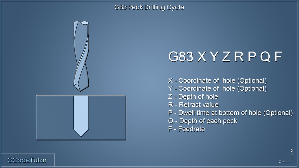
G83 X Y Z R P Q F
Example:
G83 Z-12.0 R1.0 P1000 Q3.0 F50.0;
X50.0;
X50.0;
Y40.0;
G80;
The G83 roughing cycle allows for the production of holes using a peck drilling sequence. A hole is drilling a set amount defined by the Q value then retracts to the position of the R value before continuing to drill the hole until the full depth is reached that is set using the Z value.
This is used when the depth of the hole is deep enough to cause swarf build up, as this cycle chips the swarf.
The R-value is the distance from the datum in Z to the tip of the drill. When the datum is set to the surface of the part, this dimension would be the distance from the surface of the part to the tip of the drill.
G84 - Rigid Tapping Cycle
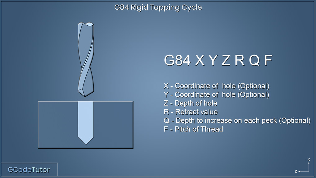
G84 X Y Z R Q F;
Example:
G84 Z-12.0 R5.0 F0.8;
X50.0;
X50.0;
Y40.0
G80;
The G84 rigid tapping cycle used to produce threads in holes without the use of a tapping head.
By adding a Q value we can turn this tapping cycle into a peck tapping cycle. The machine will tap the amount specified by the Q value before reversing out of the hole to the dimension defined by R. Then continue tapping until the full depth (Z) has been achieved.
For more information check out the G84 - Rigid Tapping Cycle article.
G85 - Boring Cycle
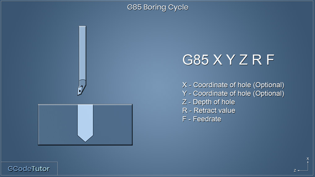
G85 X Y Z R F;
Example:
G85 Z-8.0 R1.0 F30.0;
X50.0;
X50.0 Z-5.0;
Y40.0 Z-6.0;
G80;
The G85 boring cycle bores the hole then feeds out giving a spring cut. The above example demonstrates boring four holes at three different depths.
G86- Boring Cycle
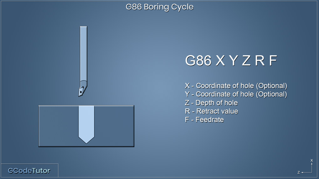
G86 X Y Z R F;
Example:
G86 Z-8.0 R1.0 F30.0;
X50.0;
X50.0;
Y40.0;
G80;
The G86 boring cycle differs from the G85 boring cycle because it bores the hole then stops the spindle before it rapid travels out to the R value, where the G85 cycle bores in then bore out.
Share this article
For a complete tutorial on CNC mill Programming check out my course.
The quickest way to learn CNC Programming


